A common misunderstanding is that a communications system comprises only a radio; that's not necessarily true. A radio is often a part of a communication system but there are normally many other parts as well. A Communications System (comms system) takes information and transfers it from one place to another. The information can be in many forms, but commonly it is spoken voice or digital data, and it can be transferred by complex or simple methods using cables, satellites, radios or even carrier pigeons or Aldis lamps!
To define the Thrust SSC team's comms system it is first necessary to define what form our information will be and where it needs to be transferred from and to. There is clearly the car itself and a `pit station', but there are also all the support team personnel, fire trucks, ambulances, chase car, tow-truck etc. Thinking of the car for a minute, Andy Green will need to speak to the `pit station', the `see-off team' (who will assist him strap into the car and carry out any last minute checks prior to the run), and the `turnround team' at the other end. These are two different requirements, as the pit is a long way away (Thrust 2 had a 13 mile track and the pit was set back 1/4 mile from the track), whereas the see-off and turnround teams will be a matter of feet away; additionally the pit should be relatively quiet (chaotic, but quiet!) and static, but the see-off team, in particular, will be moving about and after engine start will be in a very noisy environment. The car also has over 100 sensors passing information to a computer which needs to provide data to the pit station to enable the pit team to monitor the car's systems. So the system requirements are for voice and data to be passed to the pit, and voice to be passed to the see-off and turnround teams. This article is intended to be the first in a series which will look at the project's comms system and the design problems encountered along the way.
To pass voice messages over a distance of 8-10 miles from a moving vehicle to other moving vehicles and a pit station clearly requires a radio transmitter. Radio transmitters come in all sorts of shapes, sizes, power outputs and operate on different frequencies. In simple terms low frequencies signals travel further than high frequencies but the wavelength of a signal increases as frequency decreases, and aerial size is related to wavelength. Therefore, higher frequencies have smaller aerials. Unfortunately, we cannot select the best frequencies we like because in most countries frequencies are licensed from the State, this is to minimise the potential interference between different users. In America the Federal Communications Commission is responsible, and in the UK it is the Department of Trade and Industry. To comply with both country's licensing requirements, Thrust SSC has a radio which operates in the Very High Frequency (VHF) band.
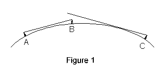
One of the drawbacks of VHF frequencies is the way in which they propagate through the atmosphere. They use what is known as the `space wave' which means they travel in almost perfectly straight lines and do not follow the curve of the earth. Figure 1 shows the limitations.

Clearly signals from transmitter `A' can be received at aerial `B' but signals from transmitter `C' cannot be received by either aerial `A' or `B' unless `A' or `B's aerials were much taller. This is the same problem that we all suffer with our vision, because light also travels in straight lines, and the maximum visible distance is limited to the Line Of Sight (LOS). VHF radio waves do in fact bend a little bit, and therefore travel a bit further - hence the radio term is known as Radio Line Of sight (RLOS). So the radio's range will be limited by the height of the transmitting and receiving aerials and the curvature of the earth. I'm ignoring any obstructions in between, such as hills, because there aren't any in the bit of desert where Thrust SSC will be running! I'm sure all you mathematicians have immediately grasped that this problem can be reduced to a formula with the aid of a bit of trigonometry. However, to save you the trouble Figure 2 is a plot of the formula that links RLOS to aerial height as a simple line graph.

The graph shows that to achieve RLOS to a point on the earth's surface 7 miles away, the transmitter aerial needs to be 25ft above the ground. Whilst the transmitter power does affect range, in a large open space like the desert, RLOS will be the limiting factor. If RLOS is not achieved, then increasing the transmit power will merely push a stronger signal out into space. Enough theory, what does this mean for Thrust SSC? As it not practical to build a 25ft tower on a car that will be driving at 850 MPH, the pit station transmitter/receiver needs to have an aerial mast at least 25ft high. The aerial on the mast will be a fairly standard 1/2 wave dipole as used on many ground installations.
The car aerial is a little more difficult. First we need an aerial that can withstand the loads caused by air pressure at Mach 1, and not cause significant aerodynamic effects that could upset the car's stability. Additionally, it needs to provide reliable links with the pit station wherever the car is during the runs, start-up and turnround phases. We also need to be able to afford it!! The aerial is currently being manufactured and once complete I will provide more information, probably in the second article.
Adam Northcote-Wright, March 1996
 |
 |
 |
||
| Sponsored by | This site best viewed with Microsoft Internet Explorer 3 | |||